


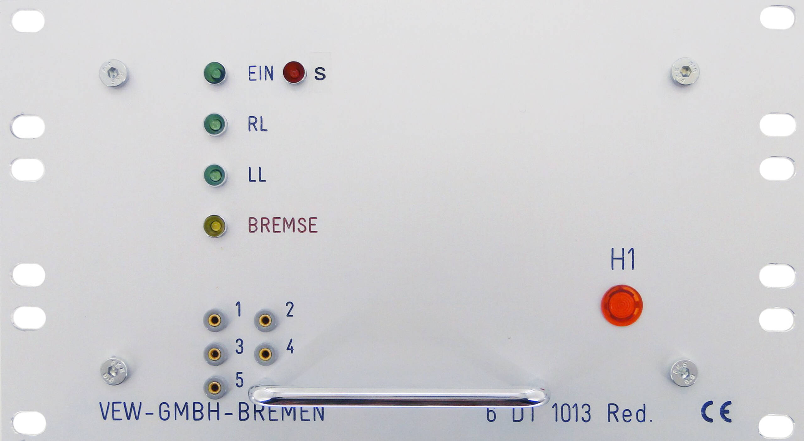
 6DT1013 2,2kW 1/2 19''
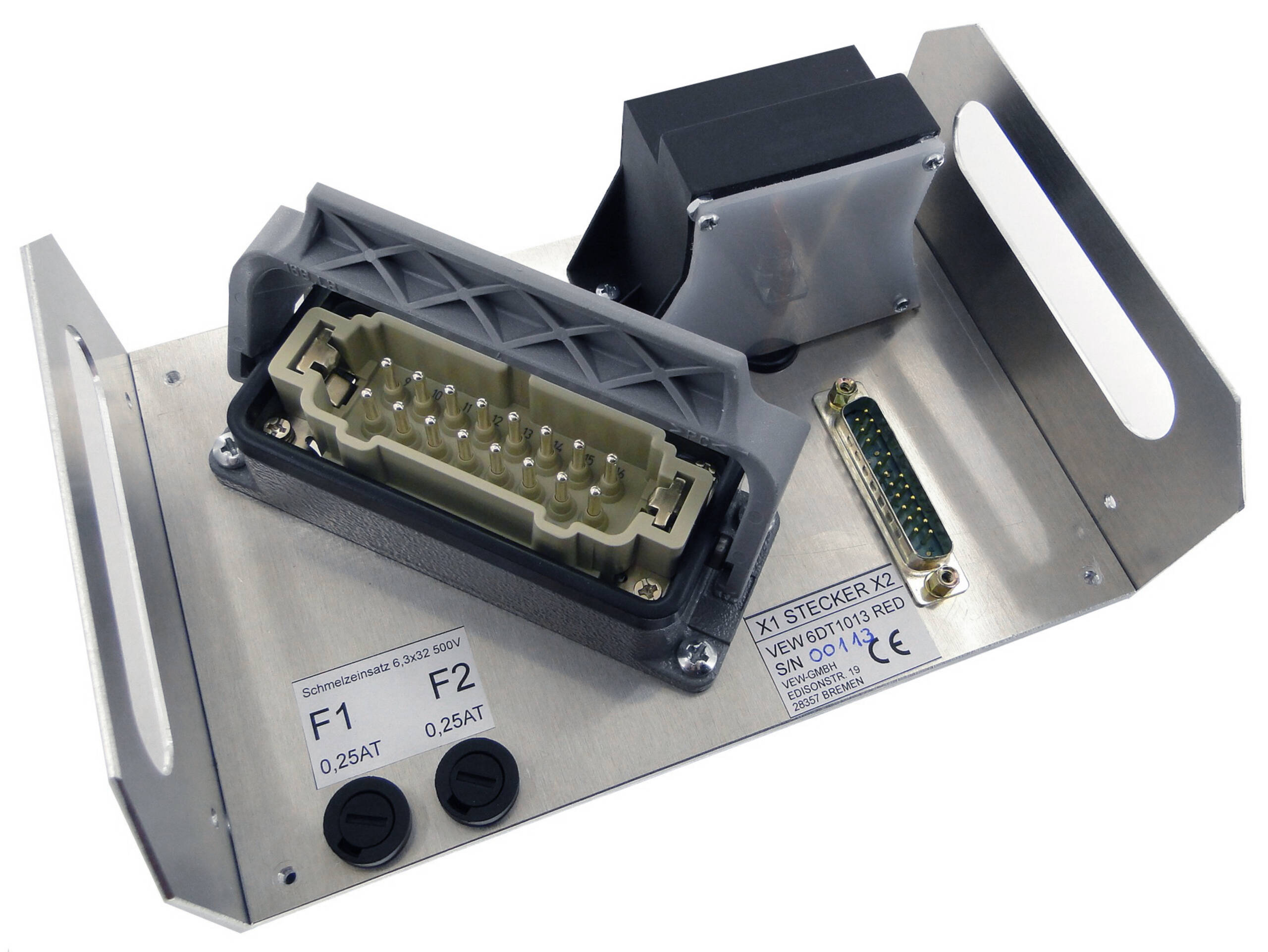
- Backside with connectors
Product Information
The original Siemens thyristor regulators with reversal contactor are no longer available. Regarding pin dimensions and functions, our newly developed and redesigned devices are fully compatible with the original, and can be installed/replaced “plug-and-play”in the existing location.
With an output rating of 2,2 kW, the units are mounted in a 3HE ½-19-inch plug-in rack, are used for step operation of motor actuators by means of DC signals from a step driver module.
The open-frame construction is designed for natural convection cooling in a control cabinet with a 50% overload rating, and an ambient temperature of max. 60°C.
The unit works as an electronic 3-phase reversal switch operated by positioning pulses and with an automatic DC brake.
The rotation direction of the connected AC actuator motor is determined by thyristor-controlled phase switching between L1 and L3.
Hereby, the respective rotation (RL-LL) and actuation of the DC brake are indicated by signalling LEDs in the front panel.
The DC brake is actuated for a adjustable duration after every positioning pulse.
The logical input conditions for RL-LL control are mutually locked.
A signal change at only one of the logic inputs during operation does not cause a change in the actuators rotation direction.
Interference pulses are suppressed.
A superordinate blocking input is provided in the rotation direction logic.
If a blocking input is set during operation, the actuator will be operated, but without the DC brake.
Moreover, the blocking input will interrupt any braking sequence.
As soon as the automatic DC brake is triggered after every positioning pulse, the preset braking sequence will start when the preset turn-off time for the thyristors has expired. Hereby, a thyristor chain is operated as a rectifier using phase-angle control, so that the motor winding generated a static magnetic field, which brakes the rotor. If the input condition for the rotation direction changes directly, the electronic brake is not triggered between the positioning pulses. Furthermore, the control unit monitors phases L1, L2 and L3, the system voltage which is generated from two phases and fuse F1 and F2.
In case of a fault, an output signal is set. If one of the thyristors are bad, an output is set and a automatic fuse interrupts the circuit.
A thermal motor protection circuit with a thermistor is provided.
Technical Data
| Supply voltage | 400V AC; 3phase; alternative 230V AC 3-phases |
| Output rating | 2,2kW for 3-phase induction motors or standard 4-pole motors |
| Inputs, logic signal | 24V level; RL-LL; blocking signal, 50ms pulse, max. 20 pulses/s |
| Brake | Dynamic DC brake, pre-adjusted 70ms, adjustable |
| Construction | 3HE 1/2 19-inch unit, openframe |
| 2 units combinable as a full 19-inch module | |
| Connectors | For logic control, Sub-D-25pole, male |
| For power output, 16-pole Harting HS12 | |
| *All product and service marks contained herein are the trademarks or service marks of their respective owners. |