Product Information
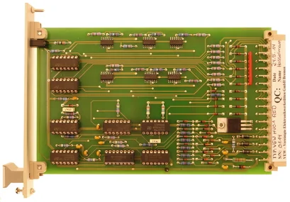
The redesign of HV01 module from H&B can be used as a plug-and-play solution instead of the original module.
The module contains 6 short-circuit resistant, monitored and no-feedback amplifiers which act as the power supply for the console modules, each with an upstream OR gate.
Each amplifier is individually monitored, e.g. for a short circuit at the outlet when a high signal occurs at the inlet, by issuing a fault notice using the standard fault detail issue, e.g. for an HP21 blinker and as collective signal S (fault) and Si (disturbing pulse) to LZ01.
The fault signals are then available decoupled via diodes. The fault is displayed with the blinking of the “S” LED on the front plate.
The function can then be tested with the LTS signal (lamp test cabinet).
The outlets of the 6 amplifiers are designed for maximum load of 200mA and protected with free-wheeling diodes, so that both the lamps and the relays can be supplied.
The outlets are not wired-or-capable.
If the channels are supplied with “blinking voltage”, a fault signal may occur in the event of a short circuit.
The power supply can have 3 voltages for redundancy.
Technical Data
| Supply voltage | +24V DC; US1 US2 VZ from LZ or UV |
| Power input | approx. 50mA + 5mA by LTS + load |
| Channel | 6, independent, decoupled, non-reactive |
| Input | Binary E1 to E6, H +24V; L 0V, LTP and LTS |
| Output |
Binary A1 to A6, H +24V; max. 200mA with protective diode; short-civcuit-proof |
| Error |
S1 to S6 for each channel S stativ; impulse for alarm system |


