


VEW PMC10/20 RED Door Control
Product description
The VEW PMC10/20 RED door control unit is a “plug and play” compatible redesign of the original control unit manufactured by IFE.
The PMC10/20 RED controls the drive unit of a double-leaf swing-sliding door used in light rail vehicles, based on binary signals from the door area (limit switches, door travel sensors, etc.), the passenger compartment (door push buttons), and the central vehicle control system.
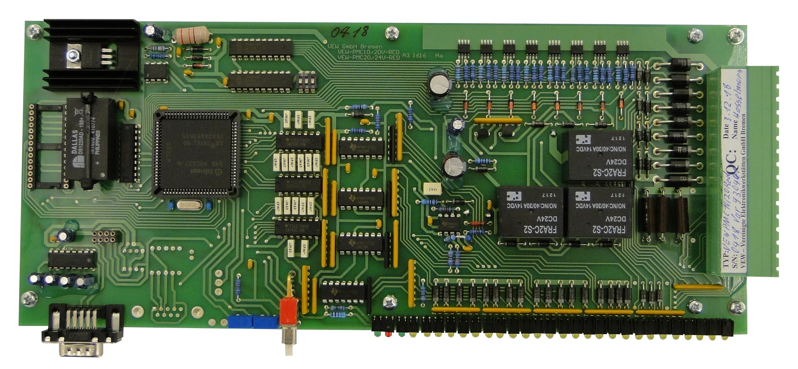
The door control unit consists of a processor-controlled logic system (with 80C537) for processing the control functions, current-limited power electronics with relay outputs for operating the electric drive, as well as 8 binary outputs using short-circuit-protected MOSFETs.
High-quality, reliable power relays from the automotive sector are used.
The control logic is fundamentally freely programmable; however, in most applications it is operated with the original controller software stored in an EPROM.
All binary states of the inputs and outputs are indicated by LEDs.
By using system-specific software provided on an EPROM that is plugged into a free socket, control requirements arising from different applications can be implemented.
The PMC10/20 RED module is supplied without an EPROM and must be equipped by the user with the EPROM containing the software for the door drive.
For data storage, a buffered CMOS RAM is used, ensuring a controlled restart after a power failure.
The VEW PMC10/20 RED module can be supplied in different versions, which can be adapted to the specific application as required.
Please send us a functional original control unit from your application.
We will check compatibility and provide you with a fully compatible sample for testing in the target application.
The original housings can continue to be used; all dimensions and mounting elements correspond to those of the original module.
The redesigned versions of the door control units are in operation in various light rail systems.
Test samples are available from stock.
Technical data
| Power supply | 24VDC ±30% |
| Controller power consumption | 150-300mA |
| Maximum motor current | 20 A, short-circuit protected |
| Binary inputs | 16; COM 0 V; with LED indicator |
| Input current | 10 mA at 24 V DC |
| Binary outputs | 8; high-side FET; with LED indicator |
| Output load | 1.5 A; short-circuit protected |
| Relay | 3; high-load relay 30/40 A |